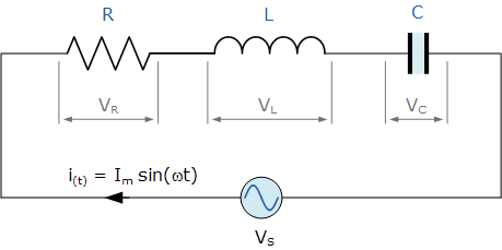
The picture below shows a RLC circuit. A RLC circuit is an electrical circuit consisting of a resistor (R), an inductor (L), and a capacitor (C), connected in series or in parallel. (1)
In order to simplify computations, it's common to work in the frequency (Laplace) domain instead of the time domain.
Your task is:
Take the values R, L and C as input, and return the voltages VR, VL and VC
The conversion to the Laplace domain is as follows:
R = R
XL = j*w*L      // OK, XL = w*L, and ZL = j*XL, but don't mind this here.
XC = 1/(j*w*C)  // I haven't ruined physics, it's only a minor terminology tweak
where j = sqrt(-1), and w = 2*pi*50 (The frequency is 50 Hz).
The combined impedance, when the components are in series is Z = R + XL + XC. You might remember U = R*I from high school physics lectures. It's almost the same, but a bit more complex now: VS = Z*I. The current is calculated by dividing the voltage VS by the total impedance Z. To find the voltage over a single component, you need to know the current, then multiply it by the impedance. For simplicity, the voltage is assumed to be VS = 1+0*j.
Equations you might need are:
XL = j*w*L
XC = 1/(j*w*C)
Z = R + XL + XC   // The combined impedance of the circuit
I = VS / Z         // The current I (Voltage divided by impedance)
VR = I * R        // Voltage over resistance (Current times resistance)
VL = I * XL       // Voltage over inductor (Current times impedance)
VC = I * XC       // Voltage over capacitor (Current times impedance)
The input is from either STDIN or as function arguments. The output/result must be three complex numbers, in a list, string or whatever is most practical in your language. It's not necessary to include names (ex VR = ...), as long as the results are in the same order as below. The precision has to be at least 3 decimal points for both the real and imaginary part. The input and output/results can be in scientific notation if that's default in your language.
R and L are >= 0, and C > 0. R, L, C <= inf (or the highest possible number in your language).
A simple test case:
R = 1, L = 1, C = 0.00001

VR = 0.0549 + 0.2277i
VL = -71.5372 +17.2353i
VC = 72.4824 -17.4630i
For the results above, this could be one (of many) valid ouput format:
(0.0549 + 0.2277i, -71.5372 +17.2353i, 72.4824 -17.4630i)
Some valid ouput formats for one voltage value are:
1.234+i1.234, 1.23456+1.23456i, 1.2345+i*1.2345, 1.234e001+j*1.234e001.
This list is not exclusive, so other variants can be used, as long as the imaginary part is indicated by an i or a j (common in electrical engineering as i is used for current).
To verify the result for other values of R,L and C, the following must be true for all results: VR + VL + VC = 1.
The shortest code in bytes win!
By the way: Yes, it's voltage over a component, and current through a component. A voltage has never gone through anything. =)

