14
\$\begingroup\$

A boolean circuit in TCS is basically a DAG consisting of And, Or, Not gates, and by what is known is "functional completeness" they can compute all possible functions. eg this is the basic principle in an ALU.

Challenge: create a circuit to determine whether an 8-binary-digit number is divisible by 3 and somehow visualize your result (ie in some kind of picture)

The judging criteria for voters is based on whether the code to generate the circuit generalizes nicely to arbitrary size numbers, and whether the algorithmically-created visualization is compact/balanced but yet still human-readable (ie visualization by hand arrangement not allowed). ie the visualization is for n=8 only but the code will ideally work for all 'n'. winning entry is just top voted.

Somewhat similar question: Build a multiplying machine using NAND logic gates

\$\endgroup\$
10
  • 2
    \$\begingroup\$ Much better. However "generalize" and "aesthetic" are not objective. All questions must have an objective winning criterion. If you want to apply those characteristics, use popularity-contest. If you want shortest code, use code-golf. If you want to make a combination of the two, use code-challenge, but specify a formula. For example 1.25*votes - 0.25*length as this question does: codegolf.stackexchange.com/questions/23581/eiffel-tower-in-3d/… \$\endgroup\$ Commented Mar 25, 2014 at 0:30
  • \$\begingroup\$ ok made those chgs you ask for. thx for feedback. \$\endgroup\$
    – vzn
    Commented Mar 25, 2014 at 1:00
  • \$\begingroup\$ Oghh, I guess compiled VHDL or Verilog after all its optimizations should give the shortest answer. I'll try it later. \$\endgroup\$ Commented Mar 25, 2014 at 6:26
  • 1
    \$\begingroup\$ A better winning criteria would be gate-golf \$\endgroup\$
    – TheDoctor
    Commented Mar 25, 2014 at 14:17
  • \$\begingroup\$ @TheDoctor ??? what is gate-golf? that tag is nonexistent. note to participants: please state what language/visualization tool you are using. if anyone else wants to enter plz comment. otherwise will accept winner tonite. thx much to respondents so far this went "BTE" better than expected! \$\endgroup\$
    – vzn
    Commented Mar 25, 2014 at 14:49

3 Answers 3

13
\$\begingroup\$

Depth:7 (logarithmic), 18x AND, 6x OR, 7x XOR, 31 gates (linear)

Let me calculate the digit sum in base four, modulo three:
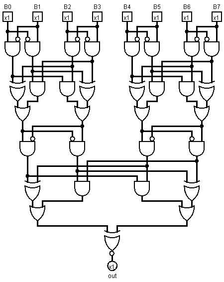
7-layer circuit with a clearly visible hierarchic structure

circuit drawn in Logisim

Generalisation, formally (hopefully somewhat readable):

balance (l, h) = {
  is1: l & not h,
  is2: h & not l,
}

add (a, b) = 
  let aa = balance (a.l, a.h)
      bb = balance (b.l, b.h)
  in  { l:(a.is2 & b.is2) | (a.is1 ^ b.is1),
        h:(a.is1 & b.is1) | (a.is2 ^ b.is2)}

pairs [] = []
pairs [a] = [{h:0, l:a}]
pairs [rest.., a, b] = [pairs(rest..).., {h:a, l:b}]

mod3 [p] = p
mod3 [rest.., p1, p2] = [add(p1, p2), rest..]

divisible3 number =
  let {l: l, h: h} = mod3 $ pairs number
  in  l == h

now in english:

While there are more than two bits in the number, take two lowest pairs of bits and sum them modulo 3, then append the result to the back of the number, then return if the last pair is zero modulo 3. If there is an odd number of bits in the number, add an extra zero bit to the top, then polish with constant value propagation.

Appending to the back instead of to the front ensures the addition tree is a balanced tree rather than a linked list. This, in turn, ensures logarithmic depth in the number of bits: five gates and three levels for pair cancellation, and an extra gate at the end.

Of course, if approximate planarity is desired, pass the top pair unmodified to the next layer instead of wrapping it to the front. This is easier said than implemented (even in pseudocode), however. If the number of bits in a number is a power of two (as is true in any modern computer system as of March 2014), no lone pairs will occur, however.

If the layouter preserves locality / performs route length minimisation, it should keep the circuit readable.

This Ruby code will generate a circuit diagram for any number of bits (even one). To print, open in Logisim and export as image:

require "nokogiri"

Port = Struct.new :x, :y, :out
Gate = Struct.new :x, :y, :name, :attrs
Wire = Struct.new :sx, :sy, :tx, :ty

puts "Please choose the number of bits: "
bits = gets.to_i

$ports = (1..bits).map {|x| Port.new 60*x, 40, false};
$wires = [];
$gates = [];

toMerge = $ports.reverse;

def balance a, b
y = [a.y, b.y].max
$wires.push Wire.new(a.x   , a.y , a.x   , y+20),
          Wire.new(a.x   , y+20, a.x   , y+40),
          Wire.new(a.x   , y+20, b.x-20, y+20),
          Wire.new(b.x-20, y+20, b.x-20, y+30),
          Wire.new(b.x   , b.y , b.x   , y+10),
          Wire.new(b.x   , y+10, b.x   , y+40),
          Wire.new(b.x   , y+10, a.x+20, y+10),
          Wire.new(a.x+20, y+10, a.x+20, y+30)
$gates.push Gate.new(a.x+10, y+70, "AND Gate", negate1: true),
          Gate.new(b.x-10, y+70, "AND Gate", negate0: true)
end

def sum (a, b, c, d)
y = [a.y, b.y, c.y, d.y].max
$wires.push Wire.new(a.x   , a.y , a.x   , y+40),
          Wire.new(a.x   , y+40, a.x   , y+50),
          Wire.new(a.x   , y+40, c.x-20, y+40),
          Wire.new(c.x-20, y+40, c.x-20, y+50),
          Wire.new(b.x   , b.y , b.x   , y+30),
          Wire.new(b.x   , y+30, b.x   , y+50),
          Wire.new(b.x   , y+30, d.x-20, y+30),
          Wire.new(d.x-20, y+30, d.x-20, y+50),
          Wire.new(c.x   , c.y , c.x   , y+20),
          Wire.new(c.x   , y+20, c.x   , y+50),
          Wire.new(c.x   , y+20, a.x+20, y+20),
          Wire.new(a.x+20, y+20, a.x+20, y+50),
          Wire.new(d.x   , d.y , d.x   , y+10),
          Wire.new(d.x   , y+10, d.x   , y+50),
          Wire.new(d.x   , y+10, b.x+20, y+10),
          Wire.new(b.x+20, y+10, b.x+20, y+50)
$gates.push Gate.new(a.x+10, y+90, "XOR Gate"),
          Gate.new(b.x+10, y+80, "AND Gate"),
          Gate.new(c.x-10, y+80, "AND Gate"),
          Gate.new(d.x-10, y+90, "XOR Gate")
$wires.push Wire.new(a.x+10, y+90, a.x+10, y+100),
          Wire.new(b.x+10, y+80, b.x+10, y+90 ),
          Wire.new(b.x+10, y+90, a.x+30, y+90 ),
          Wire.new(a.x+30, y+90, a.x+30, y+100),
          Wire.new(d.x-10, y+90, d.x-10, y+100),
          Wire.new(c.x-10, y+80, c.x-10, y+90 ),
          Wire.new(c.x-10, y+90, d.x-30, y+90 ),
          Wire.new(d.x-30, y+90, d.x-30, y+100)
$gates.push Gate.new(d.x-20, y+130, "OR Gate"),
          Gate.new(a.x+20, y+130, "OR Gate")
end

def sum3 (b, c, d)
y = [b.y, c.y, d.y].max
$wires.push Wire.new(b.x   , b.y , b.x   , y+20),
          Wire.new(b.x   , y+20, b.x   , y+30),
          Wire.new(b.x   , y+20, d.x-20, y+20),
          Wire.new(d.x-20, y+20, d.x-20, y+30),
          Wire.new(c.x   , c.y , c.x   , y+60),
          Wire.new(c.x   , y+60, b.x+30, y+60),
          Wire.new(b.x+30, y+60, b.x+30, y+70),
          Wire.new(d.x   , d.y , d.x   , y+10),
          Wire.new(d.x   , y+10, d.x   , y+30),
          Wire.new(d.x   , y+10, b.x+20, y+10),
          Wire.new(b.x+20, y+10, b.x+20, y+30),
          Wire.new(b.x+10, y+60, b.x+10, y+70)
$gates.push Gate.new(b.x+10, y+60 , "AND Gate"),
          Gate.new(d.x-10, y+70 , "XOR Gate"),
          Gate.new(b.x+20, y+100, "OR Gate" )
end

while toMerge.count > 2  
puts "#{toMerge.count} left to merge"
nextToMerge = []
while toMerge.count > 3
 puts "merging four"
 d, c, b, a, *toMerge = toMerge
 balance a, b
 balance c, d
 sum *$gates[-4..-1]
 nextToMerge.push *$gates[-2..-1] 
end
if toMerge.count == 3
 puts "merging three"
 c, b, a, *toMerge = toMerge
 balance b, c
 sum3 a, *$gates[-2..-1]
 nextToMerge.push *$gates[-2..-1]
end
nextToMerge.push *toMerge
toMerge = nextToMerge
puts "layer done"
end

if toMerge.count == 2
b, a = toMerge
x = (a.x + b.x)/2
x -= x % 10
y = [a.y, b.y].max
$wires.push Wire.new(a.x , a.y , a.x , y+10),
          Wire.new(a.x , y+10, x-10, y+10),
          Wire.new(x-10, y+10, x-10, y+20),
          Wire.new(b.x , b.y , b.x , y+10),
          Wire.new(b.x , y+10, x+10, y+10),
          Wire.new(x+10, y+10, x+10, y+20)
$gates.push Gate.new(x, y+70, "XNOR Gate")
toMerge = [$gates[-1]]
end

a = toMerge[0]
$wires.push Wire.new(a.x, a.y, a.x, a.y+10)
$ports.push Port.new(a.x, a.y+10, true)

def xy (x, y)
"(#{x},#{y})"
end
circ = Nokogiri::XML::Builder.new encoding: "UTF-8" do |xml|
xml.project version: "1.0" do
xml.lib name: "0", desc: "#Base"
xml.lib name: "1", desc: "#Wiring"
xml.lib name: "2", desc: "#Gates"
xml.options
xml.mappings
xml.toolbar do
  xml.tool lib:'0', name: "Poke Tool"
  xml.tool lib:'0', name: "Edit Tool"
end #toolbar
xml.main name: "main"
xml.circuit name: "main" do
  $wires.each do |wire|
    xml.wire from: xy(wire.sx, wire.sy), to: xy(wire.tx, wire.ty)
  end #each 
  $gates.each do |gate|
    xml.comp lib: "2", name: gate.name, loc: xy(gate.x, gate.y) do
      xml.a name: "facing", val: "south"
      xml.a name: "size", val: "30"
      xml.a name: "inputs", val: "2"
      if gate.attrs
        gate.attrs.each do |name, value|
          xml.a name: name, val: value 
        end #each
      end #if
    end #comp
  end #each
  $ports.each.with_index do |port, index|
    xml.comp lib: "1", name: "Pin", loc: xy(port.x, port.y) do
      xml.a name: "tristate", val: "false"
      xml.a name: "output",   val: port.out.to_s
      xml.a name: "facing",   val: port.out ? "north" : "south"
      xml.a name: "labelloc", val: port.out ? "south" : "north"
      xml.a name: "label",    val: port.out ? "out" : "B#{index}"
    end #port
  end #each
end #circuit
end #project
end #builder

File.open "divisibility3.circ", ?w do |file|
file << circ.to_xml
end

puts "done"

finally, when asked to create an output for 32 bits, my layouter generates this. Admittedly, it's not very compact for very wide inputs:
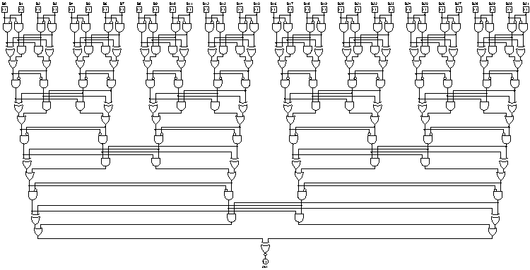
13-layer monstrosity with lots of wasted space

\$\endgroup\$
8
  • \$\begingroup\$ looks really great & best circuit/layout so far. what language is the code in? what layouter did you use if any? the layouter was requested to be an algorithm, and have to assume that algorithm was not used (hand layout) unless stated... \$\endgroup\$
    – vzn
    Commented Mar 25, 2014 at 14:54
  • \$\begingroup\$ @vzn the layouter had to be implemented, too? I understood that restriction as meaning that we could draw the diagram manually, but readability must not depend on the way the diagram is drawn. TimWolla's circuit is definitely hand-generated. The pseudo-code is mostly based on Haskell with Javascripty objects added. \$\endgroup\$ Commented Mar 25, 2014 at 15:01
  • \$\begingroup\$ algorithmically created visualization was meant to mean basically algorithmic layouter but now admit that could be ambiguously interpreted. sorry for lack of crystal clarity. do you know of any automated layouter that can get nearly similar results to your hand layout? \$\endgroup\$
    – vzn
    Commented Mar 25, 2014 at 15:30
  • \$\begingroup\$ Unfortunately, no. yEd has great layouters but it ignores orientation. I've never got familiar with dot nor I find its output exactly nice. I guess I could translate this pseudocode to Ruby (easy) and write my own specialised layouter (not too hard, but complex) that would export a logisim circuit (it's just an XML, and it's not even gzipped, so quite easy). Should I (I want to), and should I post that as a separate answer? Also, would that count as hand-designed? \$\endgroup\$ Commented Mar 25, 2014 at 15:46
  • \$\begingroup\$ All good answers, but this looks like the most elegant so far \$\endgroup\$ Commented Mar 25, 2014 at 16:42
8
\$\begingroup\$

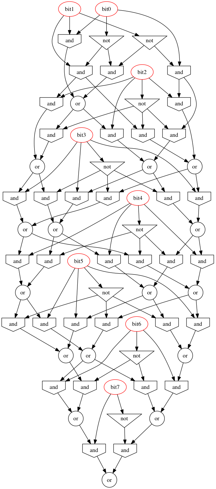
circuit to compute number modulo 3

The graph maintains 3 booleans at each level i. They represent the fact that the high-order i bits of the number are equal to 0, 1, or 2 mod 3. At each level we compute the next three bits based on the previous three bits and the next input bit.

Here's the python code that generated the graph. Just change N to get a different number of bits, or K to get a different modulus. Run the output of the python program through dot to generate the image.

N = 8
K = 3
v = ['0']*(K-1) + ['1']
ops = {}

ops['0'] = ['0']
ops['1'] = ['1']
v = ['0']*(K-1) + ['1']
for i in xrange(N):
  ops['bit%d'%i] = ['bit%d'%i]
  ops['not%d'%i] = ['not','bit%d'%i]
  for j in xrange(K):
    ops['a%d_%d'%(i,j)] = ['and','not%d'%i,v[(2*j)%K]]
    ops['b%d_%d'%(i,j)] = ['and','bit%d'%i,v[(2*j+1)%K]]
    ops['o%d_%d'%(i,j)] = ['or','a%d_%d'%(i,j),'b%d_%d'%(i,j)]
  v = ['o%d_%d'%(i,j) for j in xrange(K)]

for i in xrange(4):
  for n,op in ops.items():
    for j,a in enumerate(op[1:]):
      if ops[a][0]=='and' and ops[a][1]=='0': op[j+1]='0'
      if ops[a][0]=='and' and ops[a][2]=='0': op[j+1]='0'
      if ops[a][0]=='and' and ops[a][1]=='1': op[j+1]=ops[a][2]
      if ops[a][0]=='and' and ops[a][2]=='1': op[j+1]=ops[a][1]
      if ops[a][0]=='or' and ops[a][1]=='0': op[j+1]=ops[a][2]
      if ops[a][0]=='or' and ops[a][2]=='0': op[j+1]=ops[a][1]

for i in xrange(4):
  used = set(['o%d_0'%(N-1)])|set(a for n,op in ops.items() for a in op[1:])
  for n,op in ops.items():
    if n not in used: del ops[n]

print 'digraph {'
for n,op in ops.items():
  if op[0]=='and': print '%s [shape=invhouse]' % n
  if op[0]=='or': print '%s [shape=circle]' % n
  if op[0]=='not': print '%s [shape=invtriangle]' % n
  if op[0].startswith('bit'): print '%s [color=red]' % n
  print '%s [label=%s]' % (n,op[0])
  for a in op[1:]: print '%s -> %s' % (a,n)
print '}'
\$\endgroup\$
2
  • \$\begingroup\$ great! have used graphviz also... tiny quibble, there are unused ANDs/ORs in the diagram. also suggest maybe highlighting input bits in different color to show their locations \$\endgroup\$
    – vzn
    Commented Mar 25, 2014 at 4:08
  • \$\begingroup\$ @vzn: Ok, fixed. \$\endgroup\$ Commented Mar 25, 2014 at 5:03
6
\$\begingroup\$

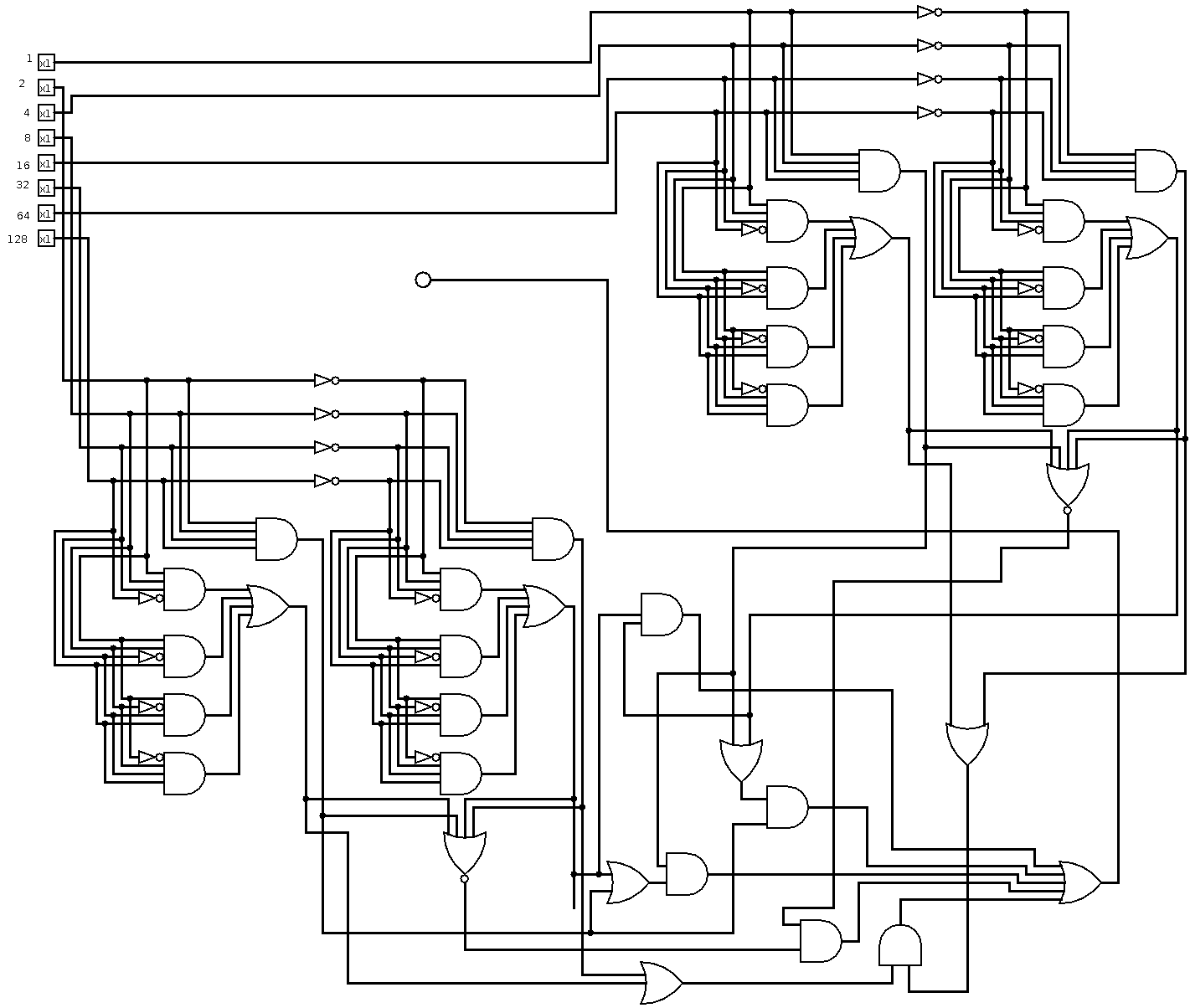
2×24 NOT, 2×10+5 AND, 2×2+5 OR, 2×2 NOR

This totally does not scale. Like not at all. Maybe I'll try to improve it.

I did test this for numbers up to 30 and it worked fine.

Those 2 big circuits are counting the number of active inputs:

  • The upper right one counts the number of bits with an even power (zero to 4)
  • The lower left one counts the number of bits with an odd power (zero to 4)

If the difference of those numbers is 0 or 3 the number is divisible by 3. The lower right circuit basically maps each valid combination (4,4, 4,1, 3,3, 3,0, 2, 2, 1, 1, 0, 0) into an or.

The little circle in the middle is an LED that is on if the number if divisible by 3 and off otherwise.

\$\endgroup\$
2
  • \$\begingroup\$ wow nice/fast! ... plz put a link to code or inline it ... also detail how you did the visualization ...? \$\endgroup\$
    – vzn
    Commented Mar 25, 2014 at 4:00
  • \$\begingroup\$ @vzn The visualization was made with logisim. It was built my hand, but the general algorithm can easily be done with a program as well. It is partly explained in the answer. \$\endgroup\$
    – TimWolla
    Commented Mar 25, 2014 at 15:05

Your Answer

By clicking “Post Your Answer”, you agree to our terms of service and acknowledge you have read our privacy policy.

Not the answer you're looking for? Browse other questions tagged or ask your own question.