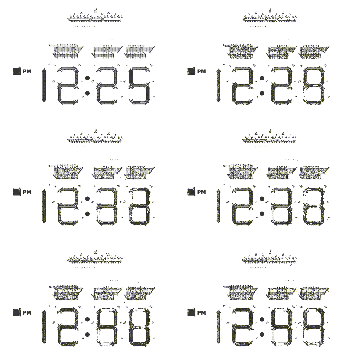
11,520 generations per clock count / 10,016 x 6,796 box / 244,596 pop count
There you go... Was fun.
Well, the design is certainly not optimal. Neither from the bounding box standpoint (those 7-segment digits are huge), nor from the initial population count (there are some useless stuff, and some stuff that could certainly be made simpler), and the execution speed - well... I'm not sure.
But, hey, it's beautiful. Look:

Run it!
Get the design from this gist. Copy the whole file text to the clipboard.
New: here is a version with both AM and PM indicators for the demanding.
Go to the online JavaScript Conway life simulator. Click import, paste the design text. You should see the design. Then, go to settings and set the generation step to 512, or something around those lines, or you'll have to wait forever to see the clock display updating.
Click run, wait a bit and be amazed!
Direct link to in-browser version.
Note that the only algorithm that makes this huge design useable is hashlife. But with this, you can achieve the whole clock wraparound in seconds. With other algorithms, it is impractical to even see the hour changing.
How it works
It uses p30 technology. Just basic things, gliders and lightweight spaceships. Basically, the design goes top-down:
- At the very top, there's the clock. It is a 11520 period clock. Note that you need about 10.000 generations to ensure the display is updated appropriately, but the design should still be stable with a clock of smaller period (about 5.000 or so - the clock needs to be multiple of 60).
- Then, there is the clock distribution stage. The clock glider is copied in a balanced tree, so at the end, there are 32 gliders arriving at the exact same moment to the counters stage.
- The counter stage is made using a RS latch for each state, and for each digit (we're counting in decimal). So there is 10 states for the right digit of the minutes, 6 states for the left digit of the minuts, and 12 states for the hours (both digits of the hours are merged here). For each of these groups, the counter behaves like a shift register.
- After the counting stage, there are the lookup tables. They convert the state pulses to display segments ON/OFF actions.
- Then, the display itself. The segments are simply made with multiple strings of LWSS. Each segment has it own latch to maintain its state. I could have made a simple logical-OR of the digit states to know wether a segment must be ON or OFF, and get rid of these latches, but there would be glitches for non-changing segments, when the digits are changing (because of signal delays). And there would be long streams of gliders coming from the lookup table to the digit segments. So it wouldn't be as nice-looking. And it needed to be. Yes.
Anyway, there is actually nothing extraordinary in this design. There are no amazing reactions that have been discovered in this process, and no really clever combinations that nobody thought of before. Just bits taken here and there and put together (and I'm not even sure I did it the "right" way - I was actually completely new to this). It required a lot of patience, however. Making all those gliders coming up at the right time in the right position was head-scratching.
Possible optimizations:
- Instead of copying and distributing the same root clock to the n counter cells, I could have just put the same clock block n times (once for each counter cell). This would actually be much simpler. But then I wouldn't be able to adjust it as easily by changing the clock at a single point... And I have an electronics background, and in a real circuit, that would be horribly wrong.
- Each segment has it own RS latch. This requires the lookup tables to output both R and S pulses. If we had a latch that would just toggle its state from a common input pulse, we could make the lookup tables half as big. There is such a latch for the PM dot, but it is huge, and I'm unable to come up with something more practical.
- Make the display smaller. But that wouldn't be as nice-looking. And it needed to be. Yes.

